Crank Bar - Applications and Benefits
- Concrete Cost Estimator
- Concrete Continuous Footing
- Landscape Bidding and Estimating
- Construction Cost Estimating
- Concrete and steel cost estimation
- Construction Cost Estimate Breakdown
- Construction Estimating Worksheet
- Home Construction Cost Estimate
- Estimate Pricing Sheet
- Sheet for General Contractor
- Construction Cost Estimate
- Labor Materials Cost Estimator
- Masonry Estimating Sheet
- Sheet for Building Contractor
- Construction Schedule Bar chart
- General Cost Estimator Sheet
- General Construction Estimate
- Building and Road Estimating Sheet
- Detailed expense estimates
- Door and Window Takeoff Sheet
- General Construction Cost Estimating Sheet

In this exclusive civil engineering article, you will get some vital information on bent up bars.
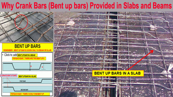
The bent up bar alias crank bars play a vital role in R.C.C beam or slabs construction because if the hogging or negative is not checked properly, the structure can collapse or the strength of the structure is minimized significantly. The hogging bending moment is produced at the supports of the slabs and beams.
BENT UP BARS:
1. Bent-up bars are arranged in the ends on the top of the slab or in the top of the mid supports (if any type of mid-support exists) to resist the negative moment known as (Hogging) developed at that sections of the slabs and beams.
2. In the slabs, there are several angles on the crank bar (known as bends). In some cases, the straight bars are arranged at the end on the top of the slab and in some cases, 45 degree angles are provided on the crank bars. In some cases, the 30° bent is arranged if there are shallow beams at the end of the slabs.
3. Usually, the crank bar are minimum 300 millimetres long and the slope or bend on the crank bars (Bent up bars) should remain 1: 10.
4. By providing crank bars in the R.C.C slabs, The Strength of the slab is raised very much from those of the slabs without having crank bars.
5. The distance among the main bars with diameter 12 mm or 10 mm should be 6 inches centre to centre c/c and if 8 mm diameter bars are applied, it should be 4-inch centre to centre c/c.
Also Read: Computation of cutting length of crank bar in slab
6. The spacing of distribution bars with diameter of 10 mm should be 9 inches to 12 inches centre to centre c/c. For 8 mm diameter bar, it should be 7 inches to 9 inches centre to centre c/c. The spacing is based on the span and thickness of slab.
CONCLUSION:
The cranks bars in slabs are provided for the following reasons :-
1. To defy Hogging alias Negative Bending Moment) at supports.
2. To address the risk of the failure of the slabs.
3. To combat the shear force. The shear force is always high in the sections of supports.
4. The crank bars are provided to enhance the strength of the slab.

- Application of concrete calculator
- Roofing Calculator can streamline the roof estimating process
- House construction cost calculator
- Engineering column design excel spreadsheet
- Material Estimating Sheet with Excel
- Materials List and Cost Estimate Worksheet
- Concrete Slab Estimating Calculator Sheet
- Common types of foundations for buildings
- Online calculation of construction materials
- Estimating with Excel for the Small Contractor
- Concrete Beam Design Spreadsheet
- Virtual Construction Management app for construction
- Autodesk’s Project Skyscraper
- Reed Construction’s Reed Insight
- Manage your construction project documentation
- Costimator, the popular cost estimating software
- On Center Software for construction professionals
- Free Construction Estimating Software
- Plumbing Calc Pro
- Cost Estimate Worksheet
- HVAC Piping Quantity Takeoff Worksheet
- Construction Estimating Software Sheet
- Estimate Cost Templates
- Construction Punch List
- Construction cost estimating template consisting estimating basic
- Gantt Chart Template for Excel
- Download Civil Engineering Spreadsheets with Verification
- The Building Advisor Estimating and Budgeting Worksheet
- Spreadsheet for design of concrete bridge
- Construction Estimating Software Free


