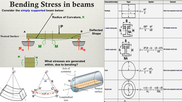
Details of Bending Stresses in beam
- Concrete Cost Estimator
- Concrete Continuous Footing
- Landscape Bidding and Estimating
- Construction Cost Estimating
- Concrete and steel cost estimation
- Construction Cost Estimate Breakdown
- Construction Estimating Worksheet
- Home Construction Cost Estimate
- Estimate Pricing Sheet
- Sheet for General Contractor
- Construction Cost Estimate
- Labor Materials Cost Estimator
- Masonry Estimating Sheet
- Sheet for Building Contractor
- Construction Schedule Bar chart
- General Cost Estimator Sheet
- General Construction Estimate
- Building and Road Estimating Sheet
- Detailed expense estimates
- Door and Window Takeoff Sheet
- General Construction Cost Estimating Sheet

Bending moment creates bending strains on a beam and as a result compressive and tensile stresses are generated. Under positive moment (as generally the case), compressive stresses are formed in the top of the beam and tensile stresses are formed in the bottom.
Bending members should withstand both compressive and tensile stresses.
For induction to bending stress, the rectangular beam and stress diagram are taken into consideration.
When the beam is dependent on some bending moment that stress at any point may be measured with the normal flexure formula : fb = Mc/I
It should be kept in mind that the above expression can only be used when the maximum calculated stress in the beam is under the elastic limit.
The above expression is given on the basis of the supposition that the stress is proportional to the strain and a plane section prior to bending remains plane once the bending is completed.
The value of I/c is a constant for specific section and is defined as the section modulus S.
The flexure formula is provided as follows :-
σ = M/S
Stress fluctuates linearly from the neutral axis to extreme fibers.
When the moment raises, there exist a linear relationship among the moment and the stress unless the stress attains the yield stress Fy
If the moment raises beyond the yield moment, the outermost fibers that was stressed earlier to their yield point will continue to get the same but will yield.
The method will persist with more and more sections of the beam cross section stressed to the yield point unless finally full plastic distribution is addressed.
The plastic moment means the moment that will create complete plasticity in a member cross section and produce a plastic hinge.
The shape factor of a member cross section is described as the proportion of the plastic moment Mp to yield moment My.
The shape factor matches 1.50 for rectangular cross sections and differs from about 1.10 to 1.20 for standard rolled beam sections.

- Application of concrete calculator
- Roofing Calculator can streamline the roof estimating process
- House construction cost calculator
- Engineering column design excel spreadsheet
- Material Estimating Sheet with Excel
- Materials List and Cost Estimate Worksheet
- Concrete Slab Estimating Calculator Sheet
- Common types of foundations for buildings
- Online calculation of construction materials
- Estimating with Excel for the Small Contractor
- Concrete Beam Design Spreadsheet
- Virtual Construction Management app for construction
- Autodesk’s Project Skyscraper
- Reed Construction’s Reed Insight
- Manage your construction project documentation
- Costimator, the popular cost estimating software
- On Center Software for construction professionals
- Free Construction Estimating Software
- Plumbing Calc Pro
- Cost Estimate Worksheet
- HVAC Piping Quantity Takeoff Worksheet
- Construction Estimating Software Sheet
- Estimate Cost Templates
- Construction Punch List
- Construction cost estimating template consisting estimating basic
- Gantt Chart Template for Excel
- Download Civil Engineering Spreadsheets with Verification
- The Building Advisor Estimating and Budgeting Worksheet
- Spreadsheet for design of concrete bridge
- Construction Estimating Software Free


