How to design and construct a septic tank
- Concrete Cost Estimator
- Concrete Continuous Footing
- Landscape Bidding and Estimating
- Construction Cost Estimating
- Concrete and steel cost estimation
- Construction Cost Estimate Breakdown
- Construction Estimating Worksheet
- Home Construction Cost Estimate
- Estimate Pricing Sheet
- Sheet for General Contractor
- Construction Cost Estimate
- Labor Materials Cost Estimator
- Masonry Estimating Sheet
- Sheet for Building Contractor
- Construction Schedule Bar chart
- General Cost Estimator Sheet
- General Construction Estimate
- Building and Road Estimating Sheet
- Detailed expense estimates
- Door and Window Takeoff Sheet
- General Construction Cost Estimating Sheet

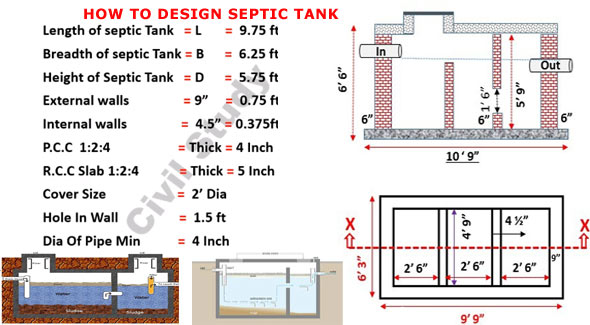
In this construction video tutorial, one can briefly learn the methods which are necessary to design and construct a septic tank.
One will be familiar with the various standard dimensions of a septic tank by studying them from a plan.
Some useful information on septic tank design
The capacity of septic tank is based on the number of users and intermission of sludge removal. Usually sludge should have been discharged every 2 years. The liquid capacity of tank is assumed as 130 liters to 70 liters per head. For small number of users 130ltr per head is assumed.
A septic tank is normally constructed with brick wall in which cement mortar [not below 20cm (9 inch)] thick and the foundation floor is made of cement concrete with 1:2:4 ratios.
Both inner and outer faces of the wall and top of the floor are plastered with cement mortar in 1:3 mix ratio by maintaining lowest thickness of 12mm (one-half inch).
All inner corners of septic tank are rounded. Water proofing agent like Impermo, Cem-seal or Accoproof etc. should have been included to the mortar at the rate of 2% of the cement weight. Water proofing agent should also be included in equivalent ratio to the concrete for building up the floor of the tank.
To collect and discharge of the sludge properly, the floor of septic tank is provided with a slope of 1:10 to 1:20 towards the inlet side. It signifies that floor of the outlet side must remain on the higher elevation as compared to the floor at inlet side. Watch the following video tutorial to learn the detail process for design and calculation.
To learn the entire process, go through the following video tutorial.
Video Source: Civil Study

- Application of concrete calculator
- Roofing Calculator can streamline the roof estimating process
- House construction cost calculator
- Engineering column design excel spreadsheet
- Material Estimating Sheet with Excel
- Materials List and Cost Estimate Worksheet
- Concrete Slab Estimating Calculator Sheet
- Common types of foundations for buildings
- Online calculation of construction materials
- Estimating with Excel for the Small Contractor
- Concrete Beam Design Spreadsheet
- Virtual Construction Management app for construction
- Autodesk’s Project Skyscraper
- Reed Construction’s Reed Insight
- Manage your construction project documentation
- Costimator, the popular cost estimating software
- On Center Software for construction professionals
- Free Construction Estimating Software
- Plumbing Calc Pro
- Cost Estimate Worksheet
- HVAC Piping Quantity Takeoff Worksheet
- Construction Estimating Software Sheet
- Estimate Cost Templates
- Construction Punch List
- Construction cost estimating template consisting estimating basic
- Gantt Chart Template for Excel
- Download Civil Engineering Spreadsheets with Verification
- The Building Advisor Estimating and Budgeting Worksheet
- Spreadsheet for design of concrete bridge
- Construction Estimating Software Free


