Splicing of Rebar - Advantages
- Concrete Cost Estimator
- Concrete Continuous Footing
- Landscape Bidding and Estimating
- Construction Cost Estimating
- Concrete and steel cost estimation
- Construction Cost Estimate Breakdown
- Construction Estimating Worksheet
- Home Construction Cost Estimate
- Estimate Pricing Sheet
- Sheet for General Contractor
- Construction Cost Estimate
- Labor Materials Cost Estimator
- Masonry Estimating Sheet
- Sheet for Building Contractor
- Construction Schedule Bar chart
- General Cost Estimator Sheet
- General Construction Estimate
- Building and Road Estimating Sheet
- Detailed expense estimates
- Door and Window Takeoff Sheet
- General Construction Cost Estimating Sheet

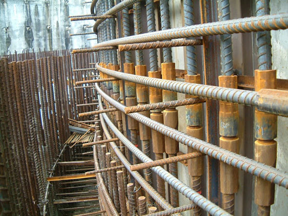
In most of the reinforced-concrete structures, rebars have to be spliced. The desired length of a bar is greater than the stock length of steel, or the bar is very long to be delivered easily. In both situations, rebar installers should use two or more pieces of steel which are spliced jointly.
The lapping of rebars is recognized as a suitable and cost-effective splicing system, but with the advent of new materials, the formation of composite materials, and the complexity of the concrete design, the builders now prefer to utilize mechanical splices in place of lap splicing.
Mechanical splices stand for mechanical connections among two pieces of rebar which facilitate the bars to perform in a manner close to continuous lengths of rebar. Mechanical splices connect rebar end-to-end and offer several benefits of a continuous piece of rebar. As compared to lap splices, they are more effective since they are not dependent on concrete for transmitting the load. With mechanical splices, it becomes easier to maintain an accurate, and consistent connection instantly and easily.
Mechanical splices can bring the following advantages :
Superior Structural Integrity: Mechanical splices can easily retain the load path continuation of the reinforcement, without any dependence on the condition or subsistence of the concrete. In order to apply splices in tensile areas, they should have the ability to retain the full strength of the rebar without developing a weak point.
So, the performance of the system is maintained all through the strain-hardening area where there is a possibility for plastic deformations. In seismic applications, mechanical splices can keep proper structural integrity when bars are stressed beyond yield, enabling the typical creation of plastic hinges.
Not dependability On Concrete For Load Transmission: In coastal areas, erosion of rebar leads to concrete delamination and spalling. As lap splices deliver load through the adjacent concrete, when the concrete takes off, the lap splice in place has failed. Mechanical splices are not dependent on the concrete for load transmission and consequently, the structural integrity is sustained.
Also Read: Detail guidelines about placing and binding reinforcing steel
Abolition of Lap Splice Computations: With mechanical splicing, one can get rid of the tiresome calculations required for finding out the exact lap lengths and the prospective calculation errors.
Curtailment Of Material Costs: Since the mechanical splices never overlap, so the quantity of rebar is less, consequently, some of the material costs are minimized significantly. This cost savings become specifically significant for the jobs where expensive epoxy- coated or galvanized bars are needed because the building codes necessitate up to 50% longer splice laps for these bars than for standard rebars.
Curtailment Of Rebar Congestion: There is a common issue with concrete placing crews that they can’t place the concrete through the rebar cages properly.
Laps efficiently double the steel to concrete ratio, and the consequent congestion can control the flow and distribution of bigger aggregate particles as well as restrict the performance of vibration. Mechanical splices can minimize this congestion to a great extent.
Reduction No. of Joints
Here should be 6 meters length for joining and it leads to a reduction of no. of laps as follow:-
1. The height of the building is taken as : 100 metres
2. Standard floor height: 3.2 metres
3. No. of laps: 100 / 3.2 = 31 laps
4. No. of coupler joints: 100 / 6 = 16 joints
5. So, the reduction in no. of laps: ((31-16)/31) x 100% = 48%
Nominal wastages of HTDBs
1. The floor height is taken as 3.2m and the lap length is taken as 1.275m
2. Length of steel bar per floor is : 3.2m + 1.275m = 4.475
3. For a 12metres steel bar, two nos of 4.475 metres length bar are arranged.
4. Balance: 12metres –4.475metres –4.475metres = 3.05metres
5. If there is a 6m bar for coupler joint, no wastage can occur. So, the wastage owing to lapping is (3.05m/12m)*100% = 25.42%

- Application of concrete calculator
- Roofing Calculator can streamline the roof estimating process
- House construction cost calculator
- Engineering column design excel spreadsheet
- Material Estimating Sheet with Excel
- Materials List and Cost Estimate Worksheet
- Concrete Slab Estimating Calculator Sheet
- Common types of foundations for buildings
- Online calculation of construction materials
- Estimating with Excel for the Small Contractor
- Concrete Beam Design Spreadsheet
- Virtual Construction Management app for construction
- Autodesk’s Project Skyscraper
- Reed Construction’s Reed Insight
- Manage your construction project documentation
- Costimator, the popular cost estimating software
- On Center Software for construction professionals
- Free Construction Estimating Software
- Plumbing Calc Pro
- Cost Estimate Worksheet
- HVAC Piping Quantity Takeoff Worksheet
- Construction Estimating Software Sheet
- Estimate Cost Templates
- Construction Punch List
- Construction cost estimating template consisting estimating basic
- Gantt Chart Template for Excel
- Download Civil Engineering Spreadsheets with Verification
- The Building Advisor Estimating and Budgeting Worksheet
- Spreadsheet for design of concrete bridge
- Construction Estimating Software Free


