How to fabricate and place tolerances for perfect reinforced concrete design
- Application of concrete calculator
- Excel Sheet for contractor estimating
- Detailed Estimates in Seconds
- Largest Dam in the World
- New Construction Cost Calculator
- Estimating with Excel for the Small Contractor
- Software for Quantity and Cost Estimation
- Concrete Slab Estimating Calculator Sheet
- Cost Analysis and Project Management
- Commercial painting contractors
- Building Advisor Estimating and Budgeting
- Material Estimating Sheet with Excel
- Estimating with Excel Part4
- Enhancing the estimating process
- 30-story building built in 15 days
- Estimating with Excel Part8
- Detailed Cost Estimates in Seconds

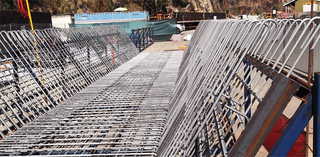
The following construction video provides information on the fabrication and tolerances required for laying reinforcing bars. By knowing this, it becomes easier to create perfect reinforced concrete design.
Placing tolerances make out the inaccurate constitution of the placing operation and contribute deviation criteria. ACI 117 specifies bar placing tolerances along with clear distance to forms and consequential concrete surfaces (differentiate with member size, 1 ⁄2 inch for members 12 to 24 inches), standardized spacing or positioning of bars in slabs or walls ( 3 inches), stirrup and tie spacing in beams and columns (one-twelfth beam depth or column width), location of bar bends and bar ends ( 2 inches, excluding 1 inch at discontinuous ends of members), length of lap splices (-11 ⁄2 inches), and embedded lengths (-1 inch for bar sizes from #3 to #11). Tolerances also are set for beam and column form dimensions.


