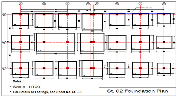
What is Foundation Drawing?
- Concrete Cost Estimator
- Concrete Continuous Footing
- Landscape Bidding and Estimating
- Construction Cost Estimating
- Concrete and steel cost estimation
- Construction Cost Estimate Breakdown
- Construction Estimating Worksheet
- Home Construction Cost Estimate
- Estimate Pricing Sheet
- Sheet for General Contractor
- Construction Cost Estimate
- Labor Materials Cost Estimator
- Masonry Estimating Sheet
- Sheet for Building Contractor
- Construction Schedule Bar chart
- General Cost Estimator Sheet
- General Construction Estimate
- Building and Road Estimating Sheet
- Detailed expense estimates
- Door and Window Takeoff Sheet
- General Construction Cost Estimating Sheet

When construction work goes on, it becomes very difficult to read a complicated drawing. Usually construction work continues on fast track and experts in construction project perform various activities to accomplish vital tasks.
They have to undertake various important decisions, develop progress reports, deal with labors, etc. They don't enough time to read the drawings properly prior to complete the construction works. Slight errors in reading the drawings leads to a major issue.
As for instance, if coordinates labeled on a foundation drawing is read improperly, the foundation will cast at incorrect location. Casting of foundation at improper coordinates will create mismatch in other interconnecting items or structural component.
Given below, some useful tips to instantly read vital information from foundation drawing.
After obtaining a foundation drawing, instantly review the following sections of the drawing to understand the drawing.
Notes: Notes given on a foundation drawing are very crucial similar to layout, sections and details of the foundation. The notes usually comprises of vital information, like specification for materials, unit of measurements, construction methodology/sequence, any special instructions, etc.
Sometimes, construction engineers and supervisors overlook these notes. But, all the notes should be read and followed throughout construction since designer choose writing notes for all those components which can't be demonstrated in details.
Acronyms:
TOG : Top of Grout
TOC : Top of Concrete
FGL : Finished Grade Level or Finished Ground level
NSL : Natural Surface Level
NGL : Natural Grade Level or Natural Ground level
Also Read: Some useful guidelines on the construction of RCC foundation
TYP. : Typical
THK. : Thick or Thickness
RCC : Reinforced Cement Concrete
CC : Cement Concrete
PCC : Plain Cement Concrete
C/C : Center to Center
T&B : Top and Bottom
B/W : Both ways
Reference Drawings/Documents: Reference drawings and documents like general notes, related specifications or any other relevant document are provided in this section. Associated drawings from other engineering disciplines, e.g. equipment GA (general arrangement), piping layouts and other electrical or mechanical drawings are also stated.
These reference documents provide several crucial information, which never be provided on each drawing because of restricted space and ease of understanding. Prior to commence the construction works, you should have proper knowledge with the reference drawings.
Cross Referencing: If there are lots of necessary details complicated in nature, all details can't be arranged in single sheet. So, all the extra details are arranged on continuation sheets. Cross referencing is given among details and layouts of several sheets. One must be familiar with cross referencing systems for the drawings to avoid overlooking of details at site. Cross referencing methods are not universal, they are project specific in nature. These methods are generally stated in project documenting process or drafting practices.
Design Information for Foundation Drawing: These details are vital parts of the foundation drawing and the site engineer should never ignore them. Given below, the detail lists of major components provided in a foundation drawings and should be studied thoroughly prior to start the construction activities.
Foundation Layout
Sections
Details
Dimensions
Reinforcement details
Coordinates (Northing & Easting)
Key plan
Anchoring details (where applicable)
General Appearance: Though these components are not so vital, but they play an important role to turn a foundation drawing acceptable. Given below, some vital features of appearance :-
Title - Template: A drawing created with defined drafting practices can be read & understood. Besides, a foundation drawing should contain a controlled drawing number, revision and signatures of engineers and draft-persons etc.

- Application of concrete calculator
- Roofing Calculator can streamline the roof estimating process
- House construction cost calculator
- Engineering column design excel spreadsheet
- Material Estimating Sheet with Excel
- Materials List and Cost Estimate Worksheet
- Concrete Slab Estimating Calculator Sheet
- Common types of foundations for buildings
- Online calculation of construction materials
- Estimating with Excel for the Small Contractor
- Concrete Beam Design Spreadsheet
- Virtual Construction Management app for construction
- Autodesk’s Project Skyscraper
- Reed Construction’s Reed Insight
- Manage your construction project documentation
- Costimator, the popular cost estimating software
- On Center Software for construction professionals
- Free Construction Estimating Software
- Plumbing Calc Pro
- Cost Estimate Worksheet
- HVAC Piping Quantity Takeoff Worksheet
- Construction Estimating Software Sheet
- Estimate Cost Templates
- Construction Punch List
- Construction cost estimating template consisting estimating basic
- Gantt Chart Template for Excel
- Download Civil Engineering Spreadsheets with Verification
- The Building Advisor Estimating and Budgeting Worksheet
- Spreadsheet for design of concrete bridge
- Construction Estimating Software Free


